Yet another power comtroller
Re: Yet another power comtroller
 by ant » Sun Jun 21, 2015 11:39 am
Done a little digging into how these things work and think some of my above assumptions are mistaken. As myles pointed out the triac is switched by a diac. A diac is like a two way zener diode so works for ac. A zener diode has a switching voltage that it won't conduct below. As I pointed out this is controlled by an R C circuit. Essentially the R C circuit determines how much voltage gets through to the diac. It is switched by volts rather than current but obviously the two go hand in hand. When you make the resistance (the pot) in the R C circuit zero then all of the changing volts in the sine wave are enough to trigger the diac and you get full power. As you turn the resistance up the smaller voltage values are not getting through enough to trigger the diac, the diac stays off and so does the triac. You are clipping your wave form. The more you turn the resistance up the higher the volts it needs to get through sufficiently to activate the diac. More and more is clipped from the waveform until eventually not enough can get through the R C circuit to trigger the diac and so the triac is always off.
The upshot of this is that I suspect the percentage you can turn down to will always be the same regardless of load size. It is voltage dependant and set by the design of the R C circuit and the gate voltage of the diac. Myles got lucky with his. So I'll only ever be able to turn down to about seven percent of any given load and it doesn't matter what load I use to calibrate the pot for optimum resolution.
What this means is that I will have finer control by running a smaller controlled element with a second uncontrolled element that can be turned on and off. This adds to the justification of the popular two element design.
If you read this far Happy Summer Solstice
The upshot of this is that I suspect the percentage you can turn down to will always be the same regardless of load size. It is voltage dependant and set by the design of the R C circuit and the gate voltage of the diac. Myles got lucky with his. So I'll only ever be able to turn down to about seven percent of any given load and it doesn't matter what load I use to calibrate the pot for optimum resolution.
What this means is that I will have finer control by running a smaller controlled element with a second uncontrolled element that can be turned on and off. This adds to the justification of the popular two element design.
If you read this far Happy Summer Solstice
-

ant - Senior Distiller

- Posts: 266
- Joined: Tue Apr 17, 2012 2:50 pm
Re: Yet another power comtroller
by Easydrinker » Sun Jun 21, 2015 11:42 pm
Just back from dancing around the stones with my Mistletoe and head on a stick...
Thanks for the detail,think I understand.
Robert.
Thanks for the detail,think I understand.
Robert.
There is no ONE way.
-

Easydrinker - Donated to StillSmart

- Posts: 5208
- Joined: Fri Jun 21, 2013 7:09 pm
- Location: The hills of lowland Scotland
- Stills: Smart & Silly
Re: Yet another power comtroller
by ant » Mon Jun 22, 2015 8:24 pm
I'm only learning this as I go along. Never looked into these before. I find as I get older I can still learn new stuff but if I don't use it for a few months it starts to get hazy again. When I was younger my memory was excellent.
Explaining how it works to you and anyone else interested enough to follow my rather detailed explanations helps set it in my own memory and gives me a reference to swot up from if I start to forget.
Good to know you both read it and follow the meaning. As you're the one who responds I think about you when I am writing. I bear in mind what we have already gone through and aim the presentation on the assumption you understood what has gone before but break any new bits down as clearly as I can understand them myself. I always remember how hard it was for me when my maths teacher would jump two or three steps on the board with a phrase like "and obviously that gives us..." Obvious in his mind maybe. Not mine. As a result of that and teacher training some many years ago, I usually try to provide complete and clear details. Except when I try to keep it short but then people can infer the wrong thing so usually long and explicit.
Explaining how it works to you and anyone else interested enough to follow my rather detailed explanations helps set it in my own memory and gives me a reference to swot up from if I start to forget.
Good to know you both read it and follow the meaning. As you're the one who responds I think about you when I am writing. I bear in mind what we have already gone through and aim the presentation on the assumption you understood what has gone before but break any new bits down as clearly as I can understand them myself. I always remember how hard it was for me when my maths teacher would jump two or three steps on the board with a phrase like "and obviously that gives us..." Obvious in his mind maybe. Not mine. As a result of that and teacher training some many years ago, I usually try to provide complete and clear details. Except when I try to keep it short but then people can infer the wrong thing so usually long and explicit.
-
ant - Senior Distiller
- Posts: 266
- Joined: Tue Apr 17, 2012 2:50 pm
Re: Yet another power comtroller
by Easydrinker » Tue Jun 23, 2015 12:52 am
Totally concurring with your pre-amble there.
These days I just junk (brain delete) stuff that I need to know at THAT time,but don't expect to use again.My head just can't hold it all.
The explicit detail that you post helps me keep up with what you are doing.
I'm not sure that I will ever use this knowledge,but it seems to be a worthy thing to be aware of.
In short,Keep it up,as long as you feel motivated.
Robert.
These days I just junk (brain delete) stuff that I need to know at THAT time,but don't expect to use again.My head just can't hold it all.
The explicit detail that you post helps me keep up with what you are doing.
I'm not sure that I will ever use this knowledge,but it seems to be a worthy thing to be aware of.
In short,Keep it up,as long as you feel motivated.
Robert.
There is no ONE way.
-
Easydrinker - Donated to StillSmart
- Posts: 5208
- Joined: Fri Jun 21, 2013 7:09 pm
- Location: The hills of lowland Scotland
- Stills: Smart & Silly
Re: Yet another power comtroller
by Anavrin » Tue Jun 23, 2015 6:59 am
Hi Ant
I remembered last night taking an oscilloscope and volt meter to my power controller and taking lots of photos for any one who was interested in seeing what effect turning the pot had on the ac waveform, my post in the threads here
viewtopic.php?f=15&t=1001&start=30#p21057
Your two way Zener diode thingy is so it can clip bothe the positive and negative cycle of the ac waveform at the same time.
I remembered last night taking an oscilloscope and volt meter to my power controller and taking lots of photos for any one who was interested in seeing what effect turning the pot had on the ac waveform, my post in the threads here
viewtopic.php?f=15&t=1001&start=30#p21057
Your two way Zener diode thingy is so it can clip bothe the positive and negative cycle of the ac waveform at the same time.

- Anavrin
- Master Distiller

- Posts: 1468
- Joined: Fri Apr 04, 2014 12:15 pm
- Location: By the Sea
- Stills: 4” StillDragon Dash
Re: Yet another power comtroller
by ant » Tue Jun 23, 2015 7:47 am
Lovely pics. I enjoyed them the first time I saw them too. Good place to reprise them just here in the discussion. Thanks for the addition.
Not exactly sure how you are meaning the comment on the diac. I think you mean it can cope with, be triggered by and switch AC becuase it can conduct or not conduct in either direction. Which is right of course.
Nothing can really be swtched at the same time though. Not exactly. All the switching events happen one after another as the power cycles. The pics on your scope are a four dimensional snap shot across time. Sorta.
What is interesting to note from the pics you took are how both the rising and falling edge of the waveform are clipped at the same point as the voltage is too low at those points to get through the R C circuit sufficiently to switch the diac on. I tend to visualise the rising edge and forget about the falling edge so your pics are a good reminder of how at low volts we are going from a smooth sine wave to that central spike which has a low average voltage but a high instant voltage while it is on. Essentially what we think is low voltage is a series of spaced out high voltage spikes. No wonder some electronics die when connected to this.
Thinking this through... You could reverse (at the design stage not one of our blocks) the output of the diac so that you clipped the middle of the wave out instead of the edges. This would provide much smoother low volts that genuinely did not rise above the average voltage set. Wonder if anyone makes those and what they would be called?
Not exactly sure how you are meaning the comment on the diac. I think you mean it can cope with, be triggered by and switch AC becuase it can conduct or not conduct in either direction. Which is right of course.
Nothing can really be swtched at the same time though. Not exactly. All the switching events happen one after another as the power cycles. The pics on your scope are a four dimensional snap shot across time. Sorta.
What is interesting to note from the pics you took are how both the rising and falling edge of the waveform are clipped at the same point as the voltage is too low at those points to get through the R C circuit sufficiently to switch the diac on. I tend to visualise the rising edge and forget about the falling edge so your pics are a good reminder of how at low volts we are going from a smooth sine wave to that central spike which has a low average voltage but a high instant voltage while it is on. Essentially what we think is low voltage is a series of spaced out high voltage spikes. No wonder some electronics die when connected to this.
Thinking this through... You could reverse (at the design stage not one of our blocks) the output of the diac so that you clipped the middle of the wave out instead of the edges. This would provide much smoother low volts that genuinely did not rise above the average voltage set. Wonder if anyone makes those and what they would be called?
-
ant - Senior Distiller
- Posts: 266
- Joined: Tue Apr 17, 2012 2:50 pm
Re: Yet another power comtroller
by Anavrin » Tue Jun 23, 2015 8:21 am
I'm not sure it's possible to clip out the middle with this sort of controller, the R C circuit only sets a delay that controls the firing angle on the triac, anymore would get super complicate and you'd need a degree in power electronics.
To get a more controllable output you would need an inverter that could vary the average power by varying the pulses without clipping the waveform, MEGA BUCKS£££
To get a more controllable output you would need an inverter that could vary the average power by varying the pulses without clipping the waveform, MEGA BUCKS£££
- Anavrin
- Master Distiller
- Posts: 1468
- Joined: Fri Apr 04, 2014 12:15 pm
- Location: By the Sea
- Stills: 4” StillDragon Dash
Re: Yet another power comtroller
by Myles » Tue Jun 23, 2015 10:56 am
I use both sorts of controllers so let me try to help.
Phase Angle Controller. Most common triggering circuit is "zero volt switching" and it has advantages for noise and interference. Basically its a proportional control device. Think of the SSR as a gate. You crack it open and it lets through a bit of current, open more and more current gets through. For each cycle of the 50Hz supply it is only on for a small part of it.
Both the output current and the output voltage vary. If you wish to calibrate these you need to measure output current and voltage between the element legs.
Burst Fired Regulator. Different thing entirely. Switch it on and it goes to FULL OUTPUT in both current and voltage. However, it stays on for a fixed time and then switches off. Then repeats, and it switches fast. What you control is how LONG it stays switched on for.
The end result is the same, because both switch many times per second, and the element averages it out, just achieved in different ways. What we have been discussing earlier is related to the switching circuit that turns the device on. There are many variations and to be honest you don't really need to know which one you have.
Just try your own controller because there will be a minimum current to HOLD it on, and there might be a higher threshold current that you need to get over to SWITCH it on.
Use any of these devices at higher power levels and please get a fan and/or heatsink. If you let out the magic smoke they stop working!!!
Phase Angle Controller. Most common triggering circuit is "zero volt switching" and it has advantages for noise and interference. Basically its a proportional control device. Think of the SSR as a gate. You crack it open and it lets through a bit of current, open more and more current gets through. For each cycle of the 50Hz supply it is only on for a small part of it.
Both the output current and the output voltage vary. If you wish to calibrate these you need to measure output current and voltage between the element legs.
Burst Fired Regulator. Different thing entirely. Switch it on and it goes to FULL OUTPUT in both current and voltage. However, it stays on for a fixed time and then switches off. Then repeats, and it switches fast. What you control is how LONG it stays switched on for.
The end result is the same, because both switch many times per second, and the element averages it out, just achieved in different ways. What we have been discussing earlier is related to the switching circuit that turns the device on. There are many variations and to be honest you don't really need to know which one you have.
Just try your own controller because there will be a minimum current to HOLD it on, and there might be a higher threshold current that you need to get over to SWITCH it on.
Use any of these devices at higher power levels and please get a fan and/or heatsink. If you let out the magic smoke they stop working!!!
-

Myles - Master Distiller
- Posts: 692
- Joined: Tue May 07, 2013 12:43 pm
Re: Yet another power comtroller
by Easydrinker » Tue Jun 23, 2015 11:20 pm
There's that magic smoke being mentioned again...
It may be mythical,or comedic,but I like to think that it exists,as it helps me get past the real stuff that I struggle with.
I don't mind doffing my cap at smarter people though.
Robert.
It may be mythical,or comedic,but I like to think that it exists,as it helps me get past the real stuff that I struggle with.
I don't mind doffing my cap at smarter people though.
Robert.
There is no ONE way.
-
Easydrinker - Donated to StillSmart
- Posts: 5208
- Joined: Fri Jun 21, 2013 7:09 pm
- Location: The hills of lowland Scotland
- Stills: Smart & Silly
Re: Yet another power comtroller
by ant » Wed Jun 24, 2015 2:30 am
It's late/earlymorning so I am too tired to discuss this properly right now but one point is that the diac is voltage controlled not current controlled. There is of course an associated and consistent (for a given load) current at the switch on point but that is not what is causing the switch. The voltage is. That is why it doesn't matter what size load you use to set up the pot. Also why it swiches on at higher currents but the same volts with larger loads. The current at switch on will vary with load size but the volts will always remain the same as it first hits the gate voltage of the diac.
If it was current controlled as you say and I initially followed then a larger load would switch at the same current as the smaller load and hence at a smaller percentage of the load. This does not happen. The percentage of load remains the same, the current doubles if the load doubles and the switch on volts remain the same independenit of load size. This is not the volts you measure. It is the internal circuit controlling the diac. The diac is voltage controlled by it's nature. Like a zener diode.
All this repetition of remains the same has me hearing Zepplin in my head; The song..
If it was current controlled as you say and I initially followed then a larger load would switch at the same current as the smaller load and hence at a smaller percentage of the load. This does not happen. The percentage of load remains the same, the current doubles if the load doubles and the switch on volts remain the same independenit of load size. This is not the volts you measure. It is the internal circuit controlling the diac. The diac is voltage controlled by it's nature. Like a zener diode.
All this repetition of remains the same has me hearing Zepplin in my head; The song..
-
ant - Senior Distiller
- Posts: 266
- Joined: Tue Apr 17, 2012 2:50 pm
Re: Yet another power comtroller
by Myles » Wed Jun 24, 2015 12:16 pm
No problem.
This may help.
http://www.electronics-tutorials.ws/power/diac.html

Its the Triac that is current controlled, not the Diac.
This may help.
http://www.electronics-tutorials.ws/power/diac.html
Its the Triac that is current controlled, not the Diac.
-
Myles - Master Distiller
- Posts: 692
- Joined: Tue May 07, 2013 12:43 pm
Re: Yet another power comtroller
by ant » Thu Jun 25, 2015 12:38 pm
Yes. That article confirms what I said above. The diac is voltage controlled and when it sees sufficient voltage it supplies current to the triac base.
However in the case of the device Anavrin scoped out, and I suspect all these encapsulated devices, the triac does not self latch and stay on for the full half cycle. So current ceases to be a control factor anywhere in the circuit. This would be why there is no switching hysteresis and they turn off at the same point they turn on without going lower than the switch on point. I assume the latching current is somehow set higher than the currents the device actually sees. Dunno really though. Just a logical guess without digging into the theory.
As can be clearly seen in his pics the triac lose conduction at the same critical voltage point on the falling edge of the half cycle as the rising edge. Whatever configuration of silicone they have used inside these devices seems somewhat novel as it does not behave in reality as the articles on standard device theory would suggest. This "triac" seems to be entirely base controlled and the "diac" appears to be doing more than providing a swich on pulse. It is holding the "triac" open while the voltage is high enough and turning it off when it drops. This suggests the "RC" circuit is more than a simple timed pulse circuit but instead acts as a variable voltage gate controlling what voltage the "diac" sees on a continuous basis. The quote marks are to highlight that we don't really know what is actually in those three functional positions. If I had to guess I would say the diac is the only one of the three that is behaving exactlly as expected.
Hence it could be inverted to clip the middle out instead of the leading and falling edge as the Chinese guy with the degree in power electronics has already done the hard work.
It's power control Jim but not as we know it.
Thank you Anavrin for taking the time to reveal that truth is stranger than theory.
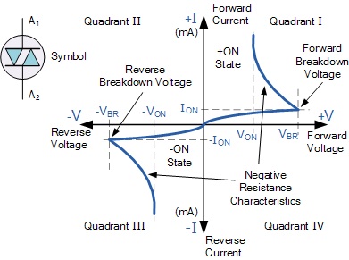
- We can see from the above diac I-V characteristics curves that the diac blocks the flow of current in both directions until the applied voltage is greater than VBR, at which point breakdown of the device occurs and the diac conducts heavily in a similar way to the zener diode passing a sudden pulse of voltage. This VBR point is called the Diacs breakdown voltage or breakover voltage.
- image.jpg (39.6 KiB) Viewed 1146 times
However in the case of the device Anavrin scoped out, and I suspect all these encapsulated devices, the triac does not self latch and stay on for the full half cycle. So current ceases to be a control factor anywhere in the circuit. This would be why there is no switching hysteresis and they turn off at the same point they turn on without going lower than the switch on point. I assume the latching current is somehow set higher than the currents the device actually sees. Dunno really though. Just a logical guess without digging into the theory.
As can be clearly seen in his pics the triac lose conduction at the same critical voltage point on the falling edge of the half cycle as the rising edge. Whatever configuration of silicone they have used inside these devices seems somewhat novel as it does not behave in reality as the articles on standard device theory would suggest. This "triac" seems to be entirely base controlled and the "diac" appears to be doing more than providing a swich on pulse. It is holding the "triac" open while the voltage is high enough and turning it off when it drops. This suggests the "RC" circuit is more than a simple timed pulse circuit but instead acts as a variable voltage gate controlling what voltage the "diac" sees on a continuous basis. The quote marks are to highlight that we don't really know what is actually in those three functional positions. If I had to guess I would say the diac is the only one of the three that is behaving exactlly as expected.
Hence it could be inverted to clip the middle out instead of the leading and falling edge as the Chinese guy with the degree in power electronics has already done the hard work.
It's power control Jim but not as we know it.
Thank you Anavrin for taking the time to reveal that truth is stranger than theory.
-
ant - Senior Distiller
- Posts: 266
- Joined: Tue Apr 17, 2012 2:50 pm
Re: Yet another power comtroller
by Anavrin » Thu Jun 25, 2015 8:08 pm
My power electronics knowledge is getting a bit rusty but I do have a HNC in electrical/electronic engineering and have worked as an engineer for almost 20 years, so hopefully this will be understandable and clear up any confusion.
Phase angle controllers use a Triac to clip the leading edge of the cycles that make up an AC sign wave, a Triac is made up of two thyristors, one in each direction so it can conduct and clip both the positive and negative cycles, due to its design only the leading edge can be clipped, and once fired by applying suficiant voltage to its gate, it will conduct until the sign wave returns to zero volts, at this point it stops conducting.
A diac is basically two diodes, again one in each direction so it two can conduct both positive and negative cycles, as a semiconductor device, it will switch on very quickly and is ideal for triggering the gate of a Triac.
Across the AC input to a power controller there will be a Resistor and a Capacitor in series with the load, the Diac is connected at one end to a point in between the Resistor and Capacitor and at the other end to the gate of the Triac.
To explain how the circuit triggers the Triac to fire and control the point on the leading edge of the cycle, it's easiest to think of just the positive half cycle : As the voltage starts to increase the capacitor is charged through the resistor, at a certain point the capacitor voltage will be enough to forward bias one of the diodes in the Diac, at this point the Diac conducts and the charge stored in the capacitor discarges through the Diac to the gate of the thyristor in the Triac, the capacitor then discarges through the Triac once it's triggered, once the gate is open, the tyristor in the triac will conduct until the end of the cycle, the voltage of the load has to return to zero before the thyristor switches off, this is why only the leading edge can be controlled.
In order to control the power to the load the value of the resistor is changed, if it's increased, it will take longer for the capacitor to charge, delaying the point at which the Diac triggers the Triac, this time delay causes the Triac to clip more of the cycle and reduce the power available to the load.
Here's a simple diagram of a phase angle controller, you can see the resistor above the capacitor on the left, the Diac connecting between the capacitor and the gate of the Traic, they show a motor as the load but it can easily be a heating element instead

It's simple and it works, trying to do anymore isnt worth the effort.
Phase angle controllers use a Triac to clip the leading edge of the cycles that make up an AC sign wave, a Triac is made up of two thyristors, one in each direction so it can conduct and clip both the positive and negative cycles, due to its design only the leading edge can be clipped, and once fired by applying suficiant voltage to its gate, it will conduct until the sign wave returns to zero volts, at this point it stops conducting.
A diac is basically two diodes, again one in each direction so it two can conduct both positive and negative cycles, as a semiconductor device, it will switch on very quickly and is ideal for triggering the gate of a Triac.
Across the AC input to a power controller there will be a Resistor and a Capacitor in series with the load, the Diac is connected at one end to a point in between the Resistor and Capacitor and at the other end to the gate of the Triac.
To explain how the circuit triggers the Triac to fire and control the point on the leading edge of the cycle, it's easiest to think of just the positive half cycle : As the voltage starts to increase the capacitor is charged through the resistor, at a certain point the capacitor voltage will be enough to forward bias one of the diodes in the Diac, at this point the Diac conducts and the charge stored in the capacitor discarges through the Diac to the gate of the thyristor in the Triac, the capacitor then discarges through the Triac once it's triggered, once the gate is open, the tyristor in the triac will conduct until the end of the cycle, the voltage of the load has to return to zero before the thyristor switches off, this is why only the leading edge can be controlled.
In order to control the power to the load the value of the resistor is changed, if it's increased, it will take longer for the capacitor to charge, delaying the point at which the Diac triggers the Triac, this time delay causes the Triac to clip more of the cycle and reduce the power available to the load.
Here's a simple diagram of a phase angle controller, you can see the resistor above the capacitor on the left, the Diac connecting between the capacitor and the gate of the Traic, they show a motor as the load but it can easily be a heating element instead
It's simple and it works, trying to do anymore isnt worth the effort.
- Anavrin
- Master Distiller
- Posts: 1468
- Joined: Fri Apr 04, 2014 12:15 pm
- Location: By the Sea
- Stills: 4” StillDragon Dash
Re: Yet another power comtroller
by Easydrinker » Thu Jun 25, 2015 10:34 pm
I think that I follow that,after a few read throughs.
Thanks Anavarin,I hope that is definitive,as another opinion could fry my brain!
Robert.
Thanks Anavarin,I hope that is definitive,as another opinion could fry my brain!
Robert.
There is no ONE way.
-
Easydrinker - Donated to StillSmart
- Posts: 5208
- Joined: Fri Jun 21, 2013 7:09 pm
- Location: The hills of lowland Scotland
- Stills: Smart & Silly
Re: Yet another power comtroller
by ant » Thu Jun 25, 2015 11:59 pm
Yes anavrin that is exactly correct. However that is not what your scope shows.
The only thing that makes sense of what your scope shows is that these are not triac based devices. They behave as though there is a high power analoge switch in them. Or perhaps a couple of mosfets back to back. A similar kind of thing either way.
They are your scope pics. Am I mistaken when I look at them and see what looks like the trailing edge of the half wave being clipped at the same point as the leading edge? Symmetrical clipping of both sides of the half wave?
A triac does not behave that way. As myles and yourself have both correctly pointed out the triac is self latching by a holding current until the zero crossover point and the trailing edge of the half wave is not clipped. Your scope clearly shows the trailing edge being clipped. Ergo not a triac. Or am I misunderstanding what your scope is showing?
The chinese have never stated these things contain a triac. We just assumed they were the same as other phase angle controller circuits. Triacs are not the only solid state power switch. Just a very common first choice.
The chinese no doubt have their reasons.
The only thing that makes sense of what your scope shows is that these are not triac based devices. They behave as though there is a high power analoge switch in them. Or perhaps a couple of mosfets back to back. A similar kind of thing either way.
They are your scope pics. Am I mistaken when I look at them and see what looks like the trailing edge of the half wave being clipped at the same point as the leading edge? Symmetrical clipping of both sides of the half wave?
A triac does not behave that way. As myles and yourself have both correctly pointed out the triac is self latching by a holding current until the zero crossover point and the trailing edge of the half wave is not clipped. Your scope clearly shows the trailing edge being clipped. Ergo not a triac. Or am I misunderstanding what your scope is showing?
The chinese have never stated these things contain a triac. We just assumed they were the same as other phase angle controller circuits. Triacs are not the only solid state power switch. Just a very common first choice.
The chinese no doubt have their reasons.
-
ant - Senior Distiller
- Posts: 266
- Joined: Tue Apr 17, 2012 2:50 pm
Who is online
Users browsing this forum: No registered users and 0 guests